RKE2: A Deep Dive into Rancher's Kubernetes Distribution
Table of Contents
- Introduction
- What is RKE2?
- How Does RKE2 Work?
- How to bootstrap an RKE2 cluster
- How does the bootstrap process work under the hood?
Introduction
Welcome to this comprehensive guide on RKE2. Kubernetes is a powerful tool for orchestrating containers but it has complexities and challenges. Whether you are an experienced Kubernetes administrator or just getting started, RKE2 aims to simplify your Kubernetes experience and enhance operational efficiency.
In this blog post, we’ll explore the origins, features, and components of RKE2. We’ll provide a guide on installing and running RKE2 and conclude with some important security considerations to be aware of when deploying and maintaining your RKE2 clusters.
So let’s dive in and learn about how RKE2 can make your Kubernetes journey smoother!
What is RKE2?
RKE2, or Rancher Kubernetes Engine 2, is a Kubernetes distribution designed for scalability, reliability, and robust security. It serves as the next-generation successor to Rancher’s original Kubernetes Engine (RKE) and is built on the core ideas and code of k3s, another lightweight Kubernetes distribution. This foundation allows RKE2 to offer a simplified and streamlined Kubernetes experience while meeting the strict requirements of modern enterprises.
Origin and Background
Rancher Labs developed RKE2, intending to create an enterprise-ready Kubernetes platform. It leverages the organization’s experience with RKE and incorporates the streamlined core ideas and code of k3s. This dual heritage makes RKE2 one of the most secure and easy-to-use Kubernetes distributions, aligning it closely with essential regulatory standards such as CIS Benchmarks.
Features and Components
RKE2 comes packed with several enhancements and built-in features that are particularly useful for enterprise deployments:
Automated Provisioning: The platform simplifies the process of node provisioning and offers seamless integration with various cloud providers and existing infrastructures.
Built-in Security: With security as a foundational principle, RKE2 provides features like automatic certificate management, role-based access control, and encrypted networking right out of the box.
High Availability: Designed for fault tolerance and high availability, RKE2 ensures that your applications are consistently accessible and operational.
Extensibility: Its modular architecture means you can easily extend RKE2’s capabilities through additional Rancher or third-party services.
Simplifying Kubernetes with RKE2
Built on the core ideas and code of k3s, RKE2 significantly reduces the complexities often associated with Kubernetes:
One-Click Installations: A single command can set up a fully functional Kubernetes cluster, thanks to its k3s underpinnings.
Managed Updates: Automated updates are standard, simplifying the management of your Kubernetes deployments.
Unified Operations: Whether on-premises, in the cloud, or a hybrid environment, RKE2 offers a consistent operational experience.
Combining these features, RKE2 becomes an attractive Kubernetes solution for enterprises, blending ease of use, scalability, and stringent security measures.
How Does RKE2 Work?
Understanding the internal workings of RKE2 can provide valuable insights into its efficiency, scalability, and suitability for specific use cases. This section will offer an in-depth look at the architecture and operational mechanisms of RKE2.
Architecture Overview for RKE2
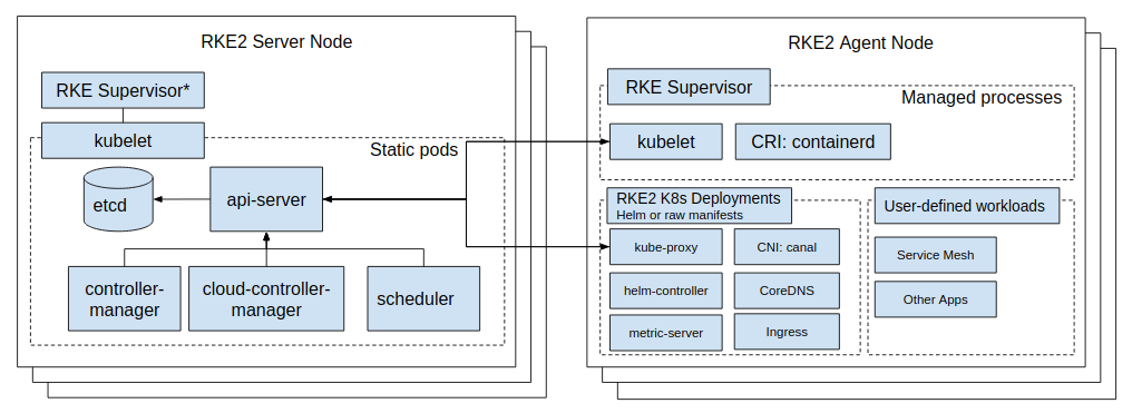
Control Plane
The control plane of RKE2 follows the standard Kubernetes architecture and comprises several key components:
RKE2 binary in Server mode: A single executable that handles bootstrapping the node and cluster, streamlining the initialization process.
Containerd: The container runtime used by RKE2 for running application workloads.
kube-apiserver (static pod): The central component that provides a RESTful interface for cluster interaction.
etcd (static pod): The database stores all cluster data, including configuration, state, and metadata.
kube-controller-manager (static pod): Manages various controllers that handle cluster operations.
kube-scheduler (static pod): Assigns workloads to nodes based on resource availability and other constraints.
cloud-controller-manager (static pod): Manages RKE2-specific resources like load balancers and volumes.
kube-proxy (static pod): Routing traffic to appropriate pods and services.
Kubelet (A binary running on the host OS): The primary node agent, managing the node and communicating with the control plane.
Worker Nodes
Worker nodes in an RKE2 cluster run application workloads and interact with the control plane to receive instructions and report statuses. The worker nodes include the following components:
RKE2 binary in Agent mode: Connecting to the control plane, registering the node with the cluster, and starting the Kubelet.
Containerd: The container runtime used to run application workloads.
RKE2 Service Load Balancer (built into the RKE2 binary): A client load balancer that provides kubelet access to the control plane nodes.
Kubelet (A binary running on the host OS): Manages the node and communicates with the control plane.
kube-proxy (static pod): Routes traffic to appropriate pods and services.
By understanding these components and their interactions, you can understand how RKE2 operates and how it fits into your organization’s specific needs.
Core Concepts of RKE2
RKE2 is built on the core ideas and code of k3s, which means it inherits many of the same concepts and mechanisms. This section will explore some of the critical concepts of RKE2 and how they can be leveraged to enhance your Kubernetes experience.
Self-Contained: RKE2 is a single binary that contains all the necessary components to run a fully functional Kubernetes cluster. IE, you should not need to install additional software to run RKE2.
Everything is a CRD: RKE2 leverages the Kubernetes Custom Resource Definition (CRD) mechanism to extend the platform’s capabilities. This approach lets you easily add new features and functionality to your RKE2 clusters.
Add-ons are helm charts: RKE2 uses Helm charts to manage add-ons IE CoreDNS, Metrics Server, etc. This approach allows you to customize these services quickly.
Static Pods: RKE2 uses static pods to run the control plane components with the basic idea that the kubelet will manage the lifecycle of these pods. This approach allows RKE2 to start pods before the control plane is fully operational.
Cluster manages itself: RKE2 is designed to be self-managing. It can automatically handle various cluster operations like nodes joining and leaving the cluster and doesn’t require external management tools like kubeadm, Rancher, config files, etc.
How to bootstrap an RKE2 cluster
Prerequisites
- A Linux host running Ubuntu 18.04 or later, CentOS 7 or later, or RHEL 7 or later.
- A user with sudo privileges.
- A minimum of 2GB of RAM and 2 CPUs.
- A minimum of 20GB of free disk space.
Installation
Install RKE2 binary
The first step is to install the RKE2 binary on the first control plane node. This can be done by running the following command:
curl -sfL https://get.rke2.io | sh -
Generate a configuration file
Next, you’ll need to generate a configuration file for your cluster. This can be done by running the following command:
mkdir -p /etc/rancher/rke2
cat <<EOF > /etc/rancher/rke2/config.yaml
write-kubeconfig-mode: "0644"
EOF
Bootstrap the cluster
Now that you have the RKE2 binary and configuration file, you can bootstrap the cluster by running the following command:
systemctl enable rke2-server.service
systemctl start rke2-server.service
Verify the cluster status
This will start the RKE2 binary in server mode and bootstrap the cluster. Once the cluster is up and running, you can verify its status by running the following command:
ln -s /var/lib/rancher/rke2/bin/kubectl /usr/local/bin/kubectl
mkdir -p ~/.kube
ln -s /etc/rancher/rke2/rke2.yaml ~/.kube/config
kubectl get nodes -o wide
NOTE: The cluster may take a few minutes to fully operational.
At this point, you should have a fully functional RKE2 cluster up and running on your host.
Add additional control plane nodes
You need to capture the cluster token on the first control plane node. NOTE: This token should be kept secret; anyone can join the cluster.
cat /var/lib/rancher/rke2/server/token
Example output:
00000000000EXAMPLE000TOKEN000REPLACE000ME00000000000000000000000000::server:12345678901234567891234567890123
You need to install the RKE2 binary on the additional control plane nodes and generate a configuration file. This can be done by running the following commands:
curl -sfL https://get.rke2.io | sh -
Generate a configuration file for the additional control plane nodes
NOTE: Replace the token with the one you captured from the first control plane node and replace the IP address with the IP address of the first control plane node.
mkdir -p /etc/rancher/rke2
cat <<EOF > /etc/rancher/rke2/config.yaml
token: REPLACE-WITH-TOKEN
server: https://REPLACE-WITH-IP-ADDRESS:9345
write-kubeconfig-mode: "0644"
EOF
Join the additional control plane nodes to the cluster
Now that you have the RKE2 binary and configuration file, you can join the additional control plane nodes to the cluster by running the following command:
systemctl enable rke2-server.service
systemctl start rke2-server.service
Verify the new control plane node status
This will start the RKE2 binary in server mode and join the additional control plane nodes to the cluster. Once the cluster is up and running, you can verify its status by running the following command:
ln -s /var/lib/rancher/rke2/bin/kubectl /usr/local/bin/kubectl
mkdir -p ~/.kube
ln -s /etc/rancher/rke2/rke2.yaml ~/.kube/config
kubectl get nodes -o wide
NOTE: The cluster may take a few minutes to fully operational; please join the control plane nodes one at a time.
At this point, you should have a fully functional RKE2 cluster with an HA control plane.
Add worker nodes
You need to capture the cluster token on the first control plane node. NOTE: This token should be kept secret; anyone can join the cluster.
curl -sfL https://get.rke2.io | INSTALL_RKE2_TYPE="agent" sh -
Generate a configuration file for the worker nodes
NOTE: Replace the token with the one you captured from the first control plane node and replace the IP address with the IP address of the first control plane node.
mkdir -p /etc/rancher/rke2
cat <<EOF > /etc/rancher/rke2/config.yaml
token: REPLACE-WITH-TOKEN
server: https://REPLACE-WITH-IP-ADDRESS:9345
EOF
Join the worker nodes in the cluster
Now that you have the RKE2 binary and configuration file, you can join the worker nodes to the cluster by running the following command:
systemctl enable rke2-agent.service
systemctl start rke2-agent.service
Verify the node status
You can verify the status of the cluster by running the following command on one of the control plane nodes:
kubectl get nodes -o wide
How does the bootstrap process work under the hood?
We use the RKE2 binary to bootstrap the cluster on the first control plane node. Once the cluster is up and running, we will be using the RKE2 binary to join the additional control plane nodes to the cluster. Finally, we are using the RKE2 binary to join the worker nodes to the cluster.
Phase 0: Generate a token
The first step is to generate a token for the cluster. The rke2 binary in server mode does this. The token is a random string of characters used to authenticate the nodes joining the cluster. The token is stored in the /var/lib/rancher/rke2/server/token file on the first control plane node. This token is also to encrypt the RKE2 data that is stored in etcd. (More on this later)
Phase 1: Generate certificates
The next step is to generate certificates for the cluster. The rke2 binary in server mode does this. This includes the kube-ca certificate, the root authority for the cluster, and the kube-apiserver certificate, which is used to authenticate the kube-apiserver to the nodes. These certificates are stored in the /var/lib/rancher/rke2/server/tls directory on the first control plane node.
Phase 2: Starting kubelet
The next step is to start the kubelet on the first control plane node. The rke2 binary in server mode does this. The kubelet connects through the RKE2 Service Load Balancer (built into the RKE2 binary) to the kube-apiserver. It will start without the kube-apiserver being fully operational. This is done by using static pods. The kubelet will create the following static pods:
- kube-apiserver
- etcd
- kube-controller-manager
- kube-scheduler
- cloud-controller-manager
NOTE: The kubelet will start these pods in the kube-system namespace.
Phase 3: Storing the state in etcd
RKE2 uses etcd to store the state of the cluster. This includes the cluster configuration, cluster state, and cluster metadata. This replaces the cluster.rkestate file used in RKE1. NOTE: The data stored in etcd is encrypted using the token generated in phase 0 and stored as key/value pairs outside of kubernetes resources.
For example, the following command will show the current control plane nodes in the cluster:
ETCD_POD=$(kubectl -n kube-system get pods -l component=etcd -o name | awk -F '/' '{print $2}' | head -n1)
kubectl -n kube-system exec -it ${ETCD_POD} -- sh
ETCDCTL_API=3 etcdctl --cert /var/lib/rancher/rke2/server/tls/etcd/server-client.crt --key /var/lib/rancher/rke2/server/tls/etcd/server-client.key --endpoints https://127.0.0.1:2379 --cacert /var/lib/rancher/rke2/server/tls/etcd/server-ca.crt get --prefix rke2/apiaddresses
rke2/apiaddresses
Example output:
["172.28.1.21:6443","172.28.1.22:6443","172.28.1.23:6443"]
If you want to see the data stored in etcd, you can run the following command to grab the bootstrap key name:
ETCD_POD=$(kubectl -n kube-system get pods -l component=etcd -o name | awk -F '/' '{print $2}' | head -n1)
kubectl -n kube-system exec -it ${ETCD_POD} -- sh
ETCDCTL_API=3 etcdctl --cert /var/lib/rancher/rke2/server/tls/etcd/server-client.crt --key /var/lib/rancher/rke2/server/tls/etcd/server-client.key --endpoints https://127.0.0.1:2379 --cacert /var/lib/rancher/rke2/server/tls/etcd/server-ca.crt get --prefix / --keys-only | grep "bootstrap/"
Example output:
/bootstrap/1ddccf194dd2
NOTE: The bootstrap key name is the key name is a hash of the token.
Now that we have the bootstrap key name, we can run the following command to see the data stored in etcd:
ETCD_POD=$(kubectl -n kube-system get pods -l component=etcd -o name | awk -F '/' '{print $2}' | head -n1)
kubectl -n kube-system exec -it ${ETCD_POD} -- sh
ETCDCTL_API=3 etcdctl --cert /var/lib/rancher/rke2/server/tls/etcd/server-client.crt --key /var/lib/rancher/rke2/server/tls/etcd/server-client.key --endpoints https://127.0.0.1:2379 --cacert /var/lib/rancher/rke2/server/tls/etcd/server-ca.crt get /bootstrap/1ddccf194dd2
Example output:
f7224d57c687ac89:QeGJswXLsYlDV9sw5MS2wK/t/rlEVO913oEWuSZW7FKw3cFBhsBJV4CvGzH9BWbWdzgBTcx6a6MgAQMYukmqEoHpCDIH4eOMuwM3ZXicpkNHEK01G3p3/yXi6YlxVyUpv58sJTqhsYQzJmrNOB0FB7iqbI1y1+wVxMQgZTCsR0MeZYP06w/dL2O7ZnmthJQDYZDgM7PZw1RKseZHmtuNbqSNQA1n5Jp6LFtqwVzZ44LWK/y5crdBB51Yi56GijjKiPNjWC+9C/8T3RywkiEBHyGu5a2f1jFfTF4++g0z3UKejNErrDw0DhI7PPZMZX0UiRtOx9SdCz/uxa8DUXBSUsj/pDffn/p2Qne7K6ulQ6f5FSndwFLudXSu1O3BFaJppgE3K110OoOnw7O/TslIs7oJyeh5nYzPA/RHhyVpLL3ACoak9CuRUcXUfb+xg73GpVsmb2AMdiu
...
This data is in an encrypted JSON blob that contains the following information:
ClientCA:
  Content: LS0tLS1CRUdJTiBDRVJUSUZJQ0FURS0tLS0t...
  Timestamp: "2023-10-10T21:03:26.236054153-05:00"
ClientCAKey:
  Content: LS0tLS1CRUdJTiBFQyBQUklWQVRFIEtFWS0r...
  Timestamp: "2023-10-10T21:03:26.236054153-05:00"
ETCDPeerCA:
  Content: LS0tLS1CRUdJTiBDRVJUSUZJQ0FURS0tLS0r...
  Timestamp: "2023-10-10T21:03:26.264054702-05:00"
ETCDPeerCAKey:
  Content: LS0tLS1CRUdJTiBFQyBQUklWQVRFIEtFWS0r...
  Timestamp: "2023-10-10T21:03:26.264054702-05:00"
ETCDServerCA:
  Content: LS0tLS1CRUdJTiBDRVJUSUZJQ0FURS0tLS0t...
  Timestamp: "2023-10-10T21:03:26.260054624-05:00"
ETCDServerCAKey:
  Content: LS0tLS1CRUdJTiBFQyBQUklWQVRFIEtFWS0r...
  Timestamp: "2023-10-10T21:03:26.260054624-05:00"
EncryptionConfig:
  Content: eyJraW5kIjoiRW5jcnlwdGlvbkNvbmZpZ3Vr...
  Timestamp: "2023-10-10T21:03:26.596061215-05:00"
EncryptionHash:
  Content: c3RhcnQtMDRlZTY0OTliMDIyMjI5ZTU0YTcz...
  Timestamp: "2023-10-10T21:03:26.596061215-05:00"
IPSECKey:
  Content: NmFmMjJlMjNlMWZmYjc5ZDI4YjY4NDhlZGNj...
  Timestamp: "2023-10-10T21:03:26.592061136-05:00"
PasswdFile:
  Content: Njc3YjExMTg0YTRmNWFhODBkNWUzMDg2ZDI1...
  Timestamp: "2023-10-10T21:03:26.592061136-05:00"
RequestHeaderCA:
  Content: LS0tLS1CRUdJTiBDRVJUSUZJQ0FURS0tLS0t...
  Timestamp: "2023-10-10T21:03:26.260054624-05:00"
RequestHeaderCAKey:
  Content: LS0tLS1CRUdJTiBFQyBQUklWQVRFIEtFWS0t...
  Timestamp: "2023-10-10T21:03:26.256054546-05:00"
ServerCA:
  Content: LS0tLS1CRUdJTiBDRVJUSUZJQ0FURS0tLS0t...
  Timestamp: "2023-10-10T21:03:26.256054546-05:00"
ServerCAKey:
  Content: LS0tLS1CRUdJTiBFQyBQUklWQVRFIEtFWS0t...
  Timestamp: "2023-10-10T21:03:26.252054467-05:00"
ServiceKey:
  Content: LS0tLS1CRUdJTiBSU0EgUFJJVkFURSBLRVkt...
  Timestamp: "2023-10-10T21:03:26.592061136-05:00"
If you want to see the data stored in etcd, you can run the following tool to decrypt the data rke2-k3s-bootstrap-decrypt
You can find the code for encrypting/decrypting this data in the RKE2 binary here
Phase 4: Deploying the add-ons
The next step is to deploy the add-ons to the cluster. The rke2 binary in server mode does this. This includes the CoreDNS, Metrics Server, and other add-ons. These add-ons are stored in the /var/lib/rancher/rke2/server/manifests directory on all the control plane nodes.
These YAML files are HelmChart / HelmChartConfigs deployed to the cluster. The rke2 binary in server mode does this. These add-ons are stored in the /var/lib/rancher/rke2/server/manifests directory on all the control plane nodes.
The helm charts are deployed to the cluster via helm-controller
Phase 5: Waiting for the node to go into the ready state
The next step is to wait for the nodes to enter the node object’s ready state. Typically, the last time to come up is the CNI.
Phase 6: Joining the additional control plane nodes to the cluster
The next step is to join the additional control plane nodes to the cluster. The rke2 binary in server mode does this. Because we are setting the server and token in the configuration file, the rke2 binary knows it needs to join a cluster instead of bootstrapping a new one.
It starts by creating an https request to the server for the URL https://SERVER:9345/cacerts to get the root CA certificate for the cluster. This is used to verify the server certificate.
RKE2 then takes a hash for the root CA certificate and compares it to the hash stored in the token, a hex-encoded SHA256 digest of a CA bundle, and compares it to the hash in the token. If the hashes match, then RKE2 knows that it is talking to the correct server; otherwise, it will throw an error saying that the token is invalid.
The token uses the following format:
K10<CA-HASH>::<USERNAME>:<PASSWORD>
RKE2 called the URL https://SERVER:9345/v1-rke2/readyz to check if the server was ready. If the server is not ready, it will try again in 5 seconds. If the server is ready, then it will continue.
Example CURL:
curl -vks https://node:<TOKEN>@rke2-server-1:9345/v1-rke2/readyz
RKE2 then calls the URL https://SERVER:9345/v1-rke2/agent/apiservers to a list of the control plane nodes in the cluster.
curl -ks https://node:<TOKEN>@rke2-server-1:9345/v1-rke2/apiservers
Example output:
[
  "192.168.1.21:6443",
  "192.168.1.22:6443",
  "192.168.1.23:6443"
]
This is used to configure etcd to join the current control plane node to the cluster. Same with the kube-apiserver and the internal service load balancer.
You can find all the endpoints that RKE2 exposes here NOTE Replace version.Program with rke2.
Phase 7: Waiting for the node to go into the ready state
The next step is to wait for the nodes to enter the node object’s ready state. Typically, the last thing to come up is the CNI.
Phase 8: Joining the worker nodes to the cluster
The workers follow the same process as the additional control plane nodes, except they use the RKE2 binary in agent mode, which skips the etcd, kube-apiserver, etc. steps.